
Horizontal Curve in Road: Types, Elements, Formulas & Design (IRC)
Every road turns. Wherever the alignment changes direction, the straight sections are joined by a horizontal curve — and that curve decides whether a driver can hold the road at full speed or has to brake hard for a bend he cannot see around. A curve that is too sharp, too short, or built without superelevation and sight distance is not a design detail: it is an accident waiting for the first rainy night.
This article explains what a horizontal curve is, the types used on roads, every element and formula you need to design or set out a simple circular curve, the IRC minimum radii, superelevation, sight distance and transition curves — with worked examples you can check with a calculator.
What Is a Horizontal Curve?
A horizontal curve is a curve in the plan view of a road — the bend you see on a map. It connects two straight sections (tangents) that meet at an angle, so that a vehicle changes direction gradually instead of turning a sharp corner. The curve is designed in the horizontal plane, which is why it is called “horizontal” — as opposed to a vertical curve, which deals with hills and valleys in the profile.
Roads curve for practical reasons: to follow the terrain and avoid deep cutting or high filling, to go around a hill, a river, a building or a graveyard, to fit the available land, and to keep the alignment smooth enough for the design speed. A road with no curves at all is almost never possible — and a long, perfectly straight road brings its own problem: drivers get drowsy and lose attention. The alignment of a road — its straights, curves and gradients — is covered in our guide to roads and their types.
Types of Horizontal Curves
Simple circular curve. One circular arc of a single radius joining two tangents. This is the commonest curve on roads, and the one this article designs in detail.
Compound curve. Two or more circular arcs of different radii, curving in the same direction, joined end to end. Used where the terrain or an obstacle forces the radius to change along the bend. The junction of the two arcs needs care — a sudden change of radius is a surprise for the driver.
Reverse curve. Two circular arcs curving in opposite directions, joined directly or with a short tangent between them. This is the S-bend you meet on a winding hill road. The two curves must be separated by enough tangent (or a transition) for the superelevation to change from one side to the other — otherwise the vehicle is thrown first one way, then the other.
Transition curve (spiral). A curve whose radius changes gradually — from infinity on the straight to the radius of the circular curve. It is placed between the tangent and the circular arc so that the centrifugal force builds up slowly instead of hitting the driver all at once. IRC recommends the spiral (clothoid) as the transition curve; on site the cubic parabola is the common approximation because it is easier to set out. The details and length calculation are in the transition section below.
Broken-back curve. Two circular curves in the same direction separated by a short tangent. Drivers read it as one long curve and misjudge it — IRC discourages it, and a single larger curve is almost always better.
Elements of a Simple Circular Curve
Take two straights meeting at an intersection point, and fit a circular arc of radius R between them. Every point and length on that arc has a name:
| Element | Symbol | What it is |
|---|---|---|
| Point of intersection | PI | Where the two tangents would meet if extended |
| Point of curvature | PC | Where the curve starts (tangent point) |
| Point of tangency | PT | Where the curve ends (tangent point) |
| Deflection angle | Δ (delta) | The angle between the two tangents — the angle the road turns through |
| Radius | R | Radius of the circular arc, in metres |
| Tangent length | T | Distance from PC to PI (or PI to PT) |
| Length of curve | L | Distance along the arc from PC to PT |
| External distance | E | Distance from PI to the middle of the curve (the apex) |
| Mid-ordinate | M | Distance from the middle of the long chord to the middle of the curve |
| Long chord | LC | Straight distance from PC to PT |
| Degree of curve | D | Angle subtended by a fixed chord or arc length (see below) |
Formulas for a Simple Circular Curve
All of these follow from the geometry of the circle. Δ must be in the same units throughout — use radians for the length of curve, degrees for the degree-of-curve formula:
| Quantity | Formula |
|---|---|
| Tangent length | T = R × tan(Δ/2) |
| Length of curve | L = R × Δ (Δ in radians) = π × R × Δ° / 180 |
| External distance | E = R × (sec(Δ/2) − 1) |
| Mid-ordinate | M = R × (1 − cos(Δ/2)) |
| Long chord | LC = 2 × R × sin(Δ/2) |
| Degree of curve (30 m arc) | D = 1719 / R |
| Degree of curve (20 m chord) | D = 1146 / R |
Practical note: on site, the tangent length is the first thing you set out — measure T back from the intersection point along each tangent to find PC and PT, then set out the curve from there. If T is wrong, every peg after it is wrong too.
Worked Example 1: Elements of a Simple Circular Curve
A road turns through a deflection angle Δ = 60° on a curve of radius R = 300 m. Find the tangent length, length of curve, external distance, mid-ordinate, long chord and degree of curve.
Tangent length: T = R × tan(Δ/2) = 300 × tan 30° = 300 × 0.5774 = 173.2 m
Length of curve: L = R × Δ (radians) = 300 × (60 × π / 180) = 300 × 1.0472 = 314.2 m
External distance: E = R × (sec(Δ/2) − 1) = 300 × (1.1547 − 1) = 46.4 m
Mid-ordinate: M = R × (1 − cos(Δ/2)) = 300 × (1 − 0.8660) = 40.2 m
Long chord: LC = 2 × R × sin(Δ/2) = 2 × 300 × 0.5 = 300.0 m
Degree of curve: D = 1719 / R = 1719 / 300 = 5.73° (30 m arc definition)
Check the sense of these numbers: the external distance (46.4 m) is the furthest the curve pushes out from the intersection point, and the mid-ordinate (40.2 m) is slightly less — exactly as the geometry says it should be.
Degree of Curve: What It Means
The degree of curve is an old surveyor’s way of describing how sharp a bend is: it is the angle subtended at the centre by a fixed length of arc or chord. A bigger degree means a sharper curve — a 1° curve is gentle, a 6° curve is sharp.
Two definitions are in use. By the arc definition (used by IRC, with a 30 m arc), D = 1719 / R. By the chord definition (20 m chord, common in older railway and highway practice), D = 1146 / R. The two give different numbers for the same curve, so always say which definition you are using — on a road drawing in Pakistan and India, it is the arc definition (1719 / R) unless stated otherwise.
For the worked example above (R = 300 m), the chord definition would give D = 1146 / 300 = 3.82°, against 5.73° by the arc definition. Same curve, different number — which is exactly why the definition matters.
Minimum Radius of a Horizontal Curve (IRC)
A curve cannot be sharper than the minimum radius for its design speed, or vehicles will skid or overturn. The minimum radius comes from the same balance as superelevation — the centrifugal force must be held by superelevation plus side friction:
Rmin = V² / (127 × (e + f))
where V is the design speed in km/h, e is the superelevation rate and f is the coefficient of lateral friction (0.15). With the maximum superelevation of 7% for plain and rolling terrain, the ruling minimum radii in IRC 66 are:
| Design speed (km/h) | Ruling minimum radius (m) | Absolute minimum radius (m) |
|---|---|---|
| 100 | 360 | 230 |
| 80 | 230 | 155 |
| 65 | 155 | 90 |
| 50 | 90 | 60 |
| 40 | 60 | 45 |
| 30 | 30 | 20 |
The ruling minimum radius is the value to design to. The absolute minimum radius is the smallest radius IRC allows at all — used only where the terrain or built-up area leaves no choice, and never as a routine value. If your alignment needs a radius below the absolute minimum, change the alignment: no amount of superelevation will make it safe. Values below are the IRC 66 ruling and absolute minima for the road class and terrain matching each design speed.
Our superelevation article explains the same formula from the superelevation side, including the maximum superelevation values (7% for plain and rolling terrain, 4% in urban areas, 10% in hilly terrain) and a worked example.
Worked Example 2: Minimum Radius for 80 km/h
Find the minimum radius for a national highway in plain terrain with a ruling design speed of 80 km/h, maximum superelevation 7% and friction factor 0.15.
Rmin = V² / (127 × (e + f)) = 80² / (127 × (0.07 + 0.15)) = 6400 / (127 × 0.22) = 6400 / 27.94 = 229 m
IRC rounds this to a ruling minimum radius of 230 m. Any curve on this road must have a radius of 230 m or more; a sharper curve would need more superelevation than the 7% maximum, which IRC does not allow.
Superelevation on Horizontal Curves
Every horizontal curve needs superelevation — the outer edge of the road raised above the inner edge — so that part of the vehicle’s weight, not friction alone, holds it on the bend. Without it, the full centrifugal force falls on the tyres, and on a wet road that means skidding. The superelevation rate comes from e + f = V² / (127 × R): for a given speed and radius, a sharper curve needs more superelevation, up to the IRC maximum of 7% in plain terrain.
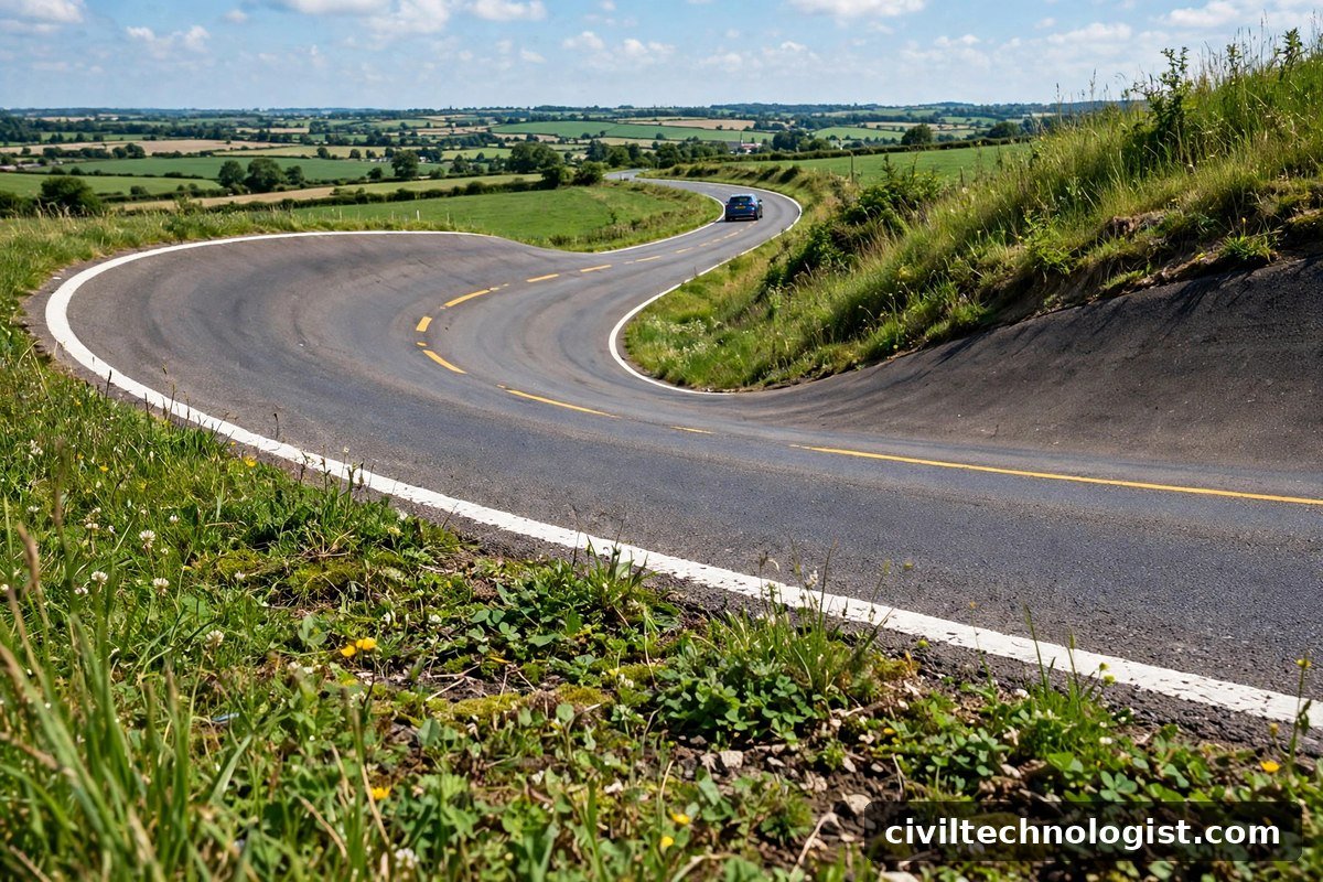
Superelevation is introduced gradually along the transition curve (or along the tangent where there is no transition), never suddenly at the start of the circular arc. A sudden step in the cross-slope is a jolt the driver feels — and on a fast road, a jolt is a loss of control. The pavement layers under the curve — the base course in particular — must follow the same alignment and cross-slope, or the finished surface will not drain. The full detail, including the maximum values, the runoff lengths and worked examples, is in our article on superelevation in roads.
Sight Distance and Setback Distance on Curves
A curve is only safe if the driver can see far enough ahead to stop. On a horizontal curve, the sight line is cut by whatever stands on the inside of the bend — a hill, a building, a wall, trees. The clear distance that must be kept free on the inside of the curve is the setback distance.
First find the stopping sight distance: SSD = 0.278 × V × t + V² / (254 × f), where V is the speed in km/h, t is the reaction time (2.5 seconds in IRC) and f is the longitudinal friction (0.35–0.40 for design). Then the setback distance for a curve of radius R is:
m = R × (1 − cos(S / 2R)) — with S / 2R in radians
For the usual case the approximate formula is close enough: m ≈ S² / (8 × R).
Worked example 3: a curve of radius R = 300 m with a stopping sight distance S = 120 m. Exact: S / 2R = 120 / 600 = 0.2 radians; cos 0.2 = 0.9801; m = 300 × (1 − 0.9801) = 6.0 m. Approximate: m ≈ 120² / (8 × 300) = 14400 / 2400 = 6.0 m. So everything within 6.0 m of the inside edge of the road, measured to the centreline of the inner lane, must be kept clear — no wall, no hoarding, no parked truck.
Practical note: setback is measured from the centreline of the inside lane, not from the edge of the road — a detail that is easy to get wrong on site and expensive to fix after the wall is built.
Transition Curves: Length and Design (IRC)
A transition curve joins the straight to the circular arc with a radius that changes gradually — infinite at the tangent end, equal to the circular radius at the curve end. It does three jobs: it lets the centrifugal force build up gradually, it gives length to introduce the superelevation, and it shifts the circular curve slightly inward (the shift) so the geometry fits.
IRC fixes the transition length as the maximum of three criteria:
1. Rate of change of centrifugal acceleration: Ls = v³ / (C × R), where v is the design speed in m/s, R is the radius in metres, and C = 80 / (75 + V) with V in km/h, limited to 0.5–0.8 m/s³.
2. Rate of introduction of superelevation: Ls = W × e × N, where W is the width of the pavement in metres, e is the superelevation rate, and N is 150 for plain and rolling terrain, 100 for built-up areas and 60 for hilly terrain.
3. IRC empirical formula: Ls = 2.7 × V² / R for plain and rolling terrain, and Ls = V² / R for hilly and steep terrain, with V in km/h and R in metres.
The shift of the circular curve — how far it moves inward to make room for the transition — is s = Ls² / (24 × R).
Worked example 4: design speed V = 80 km/h, radius R = 230 m, superelevation e = 7%, pavement width W = 7.0 m, plain terrain.
Criterion 1: v = 80 km/h = 22.22 m/s; C = 80 / (75 + 80) = 0.516 m/s³; Ls = 22.22³ / (0.516 × 230) = 10974 / 118.7 = 92.4 m
Criterion 2: Ls = 7.0 × 0.07 × 150 = 73.5 m
Criterion 3: Ls = 2.7 × 80² / 230 = 2.7 × 6400 / 230 = 75.1 m
The transition length is the maximum: Ls = 92.4 m, provide 95 m. The shift is s = 95² / (24 × 230) = 9025 / 5520 = 1.63 m.
Setting Out a Horizontal Curve on Site
Design is half the job — the curve still has to be pegged on the ground. The usual field method is the deflection-angle method with a theodolite: set up at the point of curvature, turn off the deflection angle for each chord point, and measure the chord length along that line. For a 30 m chord on a curve of radius R, the deflection angle per chord is half the degree of curve — 1719 / (2 × R) degrees (for R = 300 m, that is 2.87° per chord).
Three checks that save a setting-out job: first, the tangent length from the intersection point must land exactly on your PC and PT pegs — if it does not, the intersection point or the deflection angle is wrong, and no peg after that can be trusted. Second, the mid-point of the curve (the apex) must sit at the external distance E from the intersection point, on the line that bisects the deflection angle. Third, after setting out, measure the long chord between PC and PT and compare it with 2 × R × sin(Δ/2) — a mismatch here means a peg is out, and it is far cheaper to find it now than after the asphalt is laid.
Common Mistakes in Horizontal Curve Design
Radius below the absolute minimum. The commonest error on hill roads and housing schemes: a bend squeezed in to save land. If the radius is below the IRC absolute minimum for the design speed, the road is unsafe at that speed — lower the design speed with signs and enforcement, or realign.
No transition curve. Joining a tangent straight to a circular arc throws the full centrifugal force at the driver in one instant. On fast roads, always provide a transition; IRC requires it wherever the radius is below the value that needs no superelevation.
Superelevation introduced too fast. The runoff length is part of the design, not an afterthought. If the cross-slope changes over too short a length, the vehicle rolls and the driver corrects — on a wet night, that correction is the accident.
Sight distance forgotten. A curve designed perfectly on paper is still dangerous if a building or a cutting sits inside the setback distance. Check the setback on the plan before the land is acquired, not after the wall is built.
Broken-back curves. Two curves in the same direction with a short tangent between them read as one curve to the driver. Replace them with a single curve wherever the ground allows.
Worn or missing road marking on the curve. On a bend, the centre line and edge lines are what keep a driver in lane at night — if they are faded, the curve is twice as dangerous. The types, materials and application of road marking are covered in our road marking guide.
Quick Reference: All Formulas in One Place
| What you need | Formula |
|---|---|
| Tangent length | T = R × tan(Δ/2) |
| Length of curve | L = R × Δ (Δ in radians) |
| External distance | E = R × (sec(Δ/2) − 1) |
| Mid-ordinate | M = R × (1 − cos(Δ/2)) |
| Long chord | LC = 2 × R × sin(Δ/2) |
| Degree of curve | D = 1719 / R (30 m arc) or 1146 / R (20 m chord) |
| Minimum radius | Rmin = V² / (127 × (e + f)) |
| Superelevation | e + f = V² / (127 × R) |
| Stopping sight distance | SSD = 0.278 × V × t + V² / (254 × f) |
| Setback distance | m = R × (1 − cos(S / 2R)) ≈ S² / (8 × R) |
| Transition length | Ls = max of v³ / (C × R), W × e × N, 2.7 × V² / R |
| Shift of curve | s = Ls² / (24 × R) |
Frequently Asked Questions
What is a horizontal curve in road design?
A horizontal curve is a bend in the plan view of a road that joins two straight sections (tangents) so vehicles change direction gradually. It is designed in the horizontal plane, unlike a vertical curve, which deals with hills and valleys.
What is the formula for the minimum radius of a horizontal curve?
Rmin = V² / (127 × (e + f)), where V is the design speed in km/h, e is the superelevation rate and f is the lateral friction factor (0.15). For example, at 80 km/h with 7% superelevation, Rmin = 80² / (127 × 0.22) = 229 m, rounded to the IRC ruling value of 230 m.
What is the degree of a horizontal curve?
The degree of curve is the angle subtended at the centre by a fixed length of arc or chord — a measure of how sharp the bend is. By the arc definition used by IRC (30 m arc), D = 1719 / R; by the chord definition (20 m chord), D = 1146 / R. Always state which definition you are using.
What is a transition curve and why is it needed?
A transition curve is a curve whose radius decreases gradually from infinity (on the straight) to the radius of the circular curve. It lets centrifugal force and superelevation build up gradually instead of suddenly, and IRC fixes its length as the maximum of three criteria: rate of change of centrifugal acceleration, rate of introduction of superelevation, and the empirical formula (2.7V²/R in plain terrain).
What is the setback distance on a horizontal curve?
The setback distance is the clear distance that must be kept free on the inside of a curve so a driver can see the stopping sight distance ahead. It is m = R × (1 − cos(S / 2R)), approximately S² / (8R). For a 300 m radius curve with 120 m sight distance, the setback is about 6.0 m.
What is the difference between a horizontal curve and superelevation?
The horizontal curve is the bend itself — its radius, length and geometry. Superelevation is the banking of the road across that bend (outer edge raised) that helps hold the vehicle on the curve. Every horizontal curve needs superelevation; the sharper the curve, the more it needs, up to the IRC maximum of 7% in plain terrain.
Written by Mohsin Raza Adil — BSc Civil Engineering Technologist (NTC-registered), Pakistan.

Mohsin Raza Adil
BSc Civil Engineering Technologist (NTC-registered), Pakistan. I write practical, field-tested guides on construction materials, soil testing and site engineering — the way it is actually done on site.