After every layer of soil is compacted on site — subgrade, embankment, or a granular sub-base — the engineer asks one question: did we actually achieve the required density? The core cutter test answers it. A steel cylinder of known volume is driven into the compacted layer, the soil inside is weighed, and the field dry density is calculated and compared with the laboratory maximum dry density.
This guide covers the complete procedure with apparatus dimensions, volume calibration, the calculation with a worked example, the governing international standards, and when to choose the core cutter over the sand cone method.
What the Core Cutter Test Measures
The test determines the in-place (field) dry density of soil. From it you calculate:
- Bulk (wet) density = mass of soil in the cutter ÷ internal volume of the cutter
- Dry density = bulk density ÷ (1 + moisture content)
- Degree (percentage) of compaction = (field dry density ÷ laboratory maximum dry density) × 100
The percentage of compaction is the acceptance number on site. If the specification demands 95% compaction and your test gives 95% or more, the layer passes.
When to Use It — and When Not To
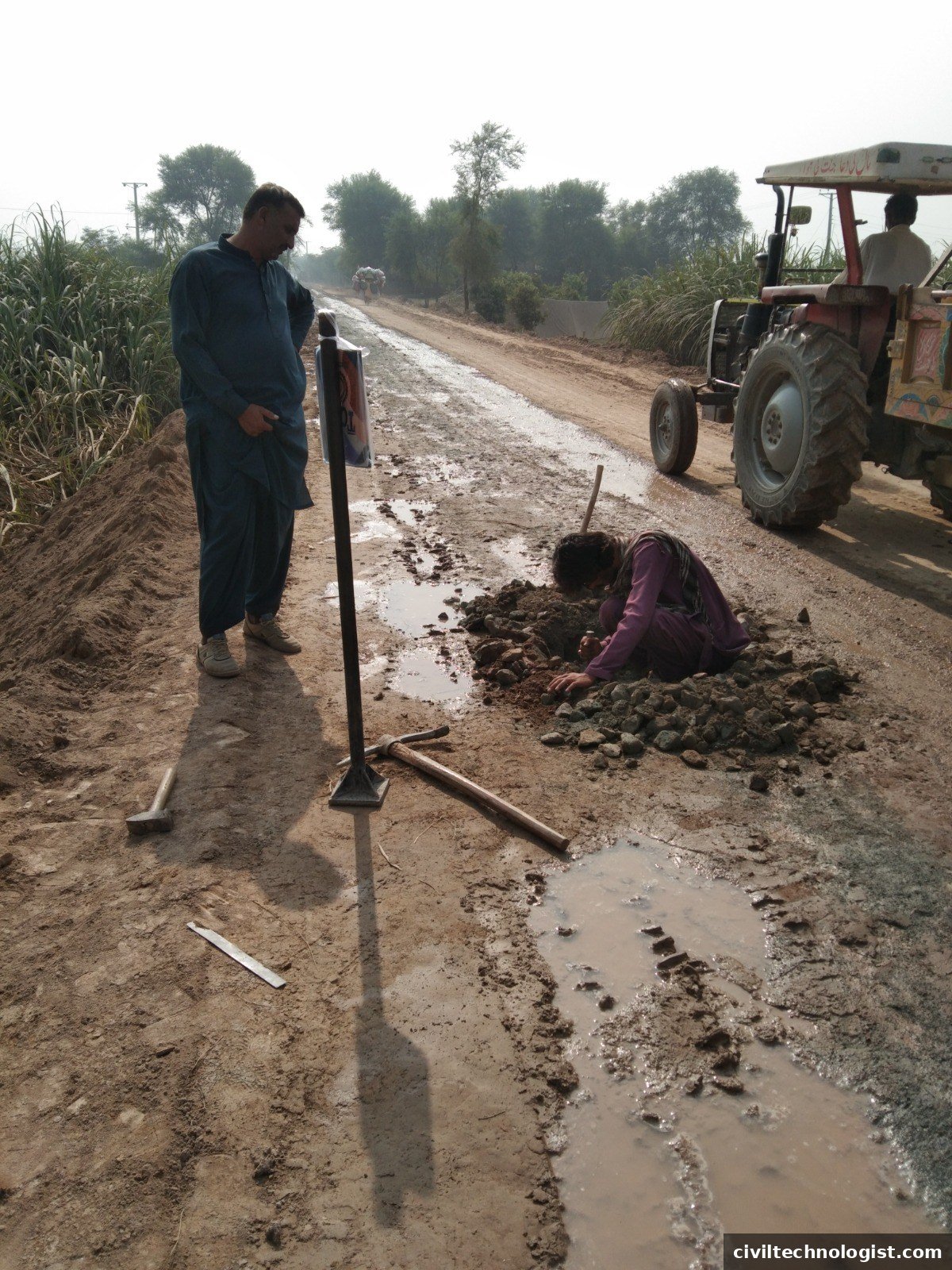
IS 2720 (Part 29) states the method is suitable for fine-grained soils free from aggregations, and makes it applicable to any soil 90% of which passes the 4.75 mm IS sieve — so clays, silts and clayey/silty sands that hold together when the cutter is driven in and trimmed, with only a small fraction of coarser particles. The standard itself adds one honest caveat: the method is less accurate than the sand replacement method, and is not recommended unless speed is essential or the soil is well compacted.
Do not use it where:
- More than about 10% of the soil is retained on the 4.75 mm sieve — gravelly, bouldery or stony ground. Coarse particles tear the sample and damage the cutting edge (ASTM D2937 likewise excludes soils with appreciable gravel coarser than 4.75 mm).
- The layer is too hard or dry to drive the cutter in without cracking the sample.
- The soil is loose, saturated sand — the sample will not stay intact. Use the sand cone (sand replacement) method instead.
Apparatus
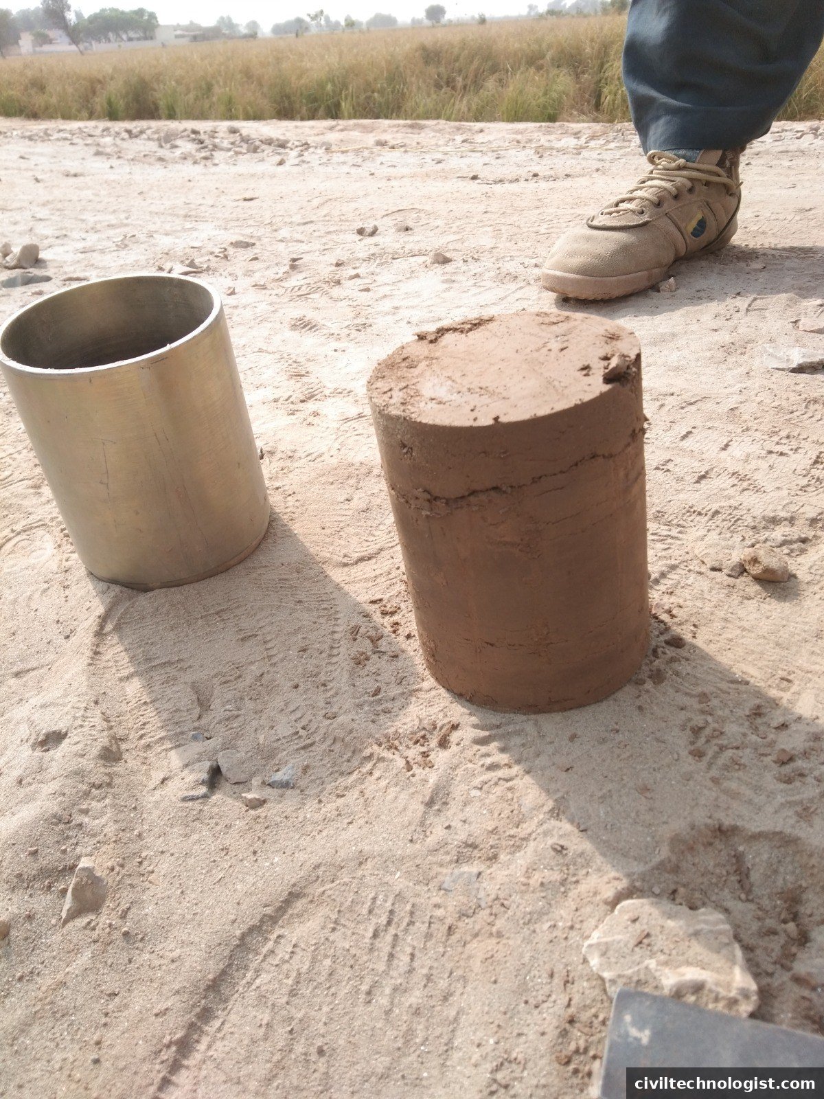
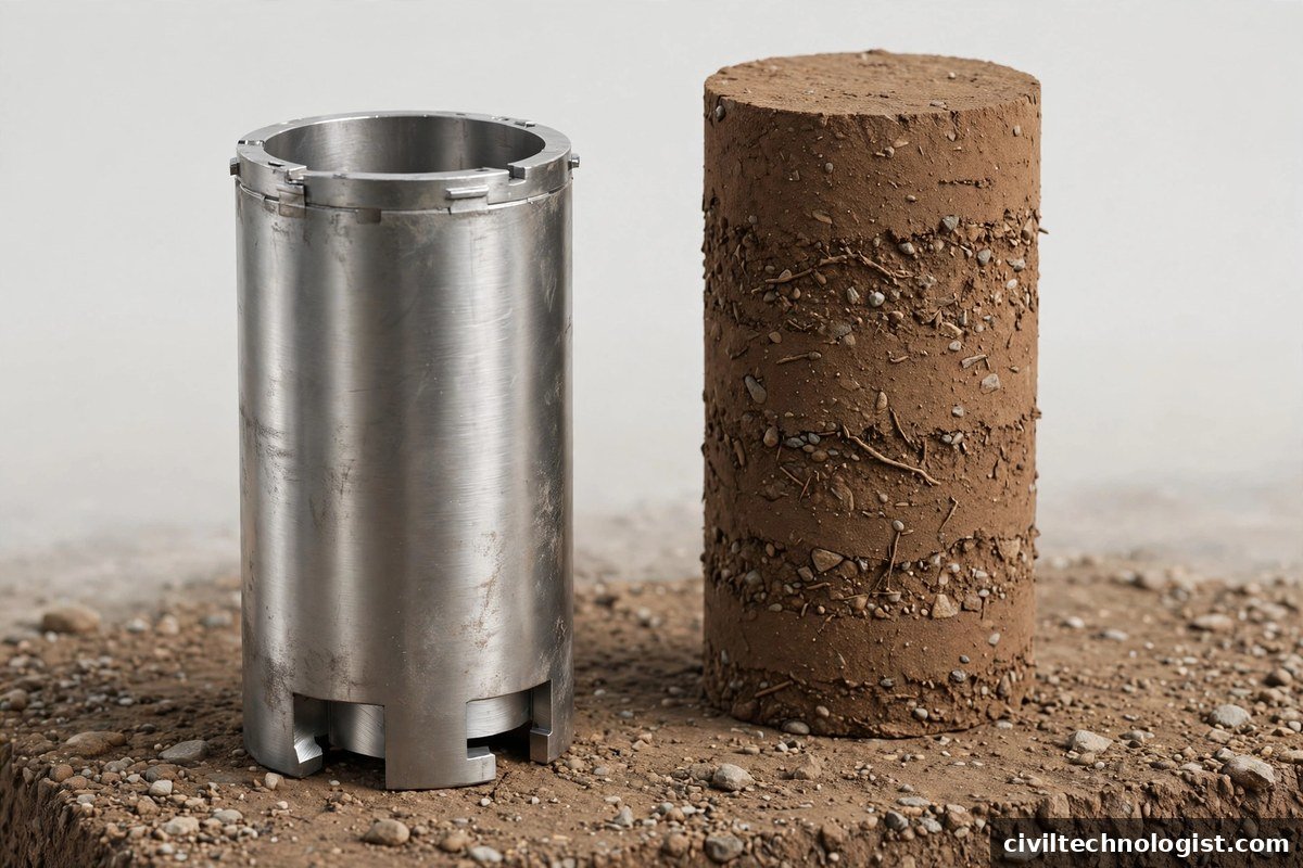
- Core cutter — a seamless steel cylinder. Per IS 2720 (Part 29): 100 mm internal diameter × 130 mm height, giving an internal volume of about 1021 cm³. The lower end is bevelled to a cutting edge.
- Steel dolly — 100 mm diameter, 25 mm high, with a 2 mm deep groove on top; placed on the cutter while driving to protect its rim.
- Rammer — for driving the cutter and dolly into the ground (IS practice: about 9 kg mass, ~900 mm overall length).
- Straightedge, knife/spatula — for trimming the soil flush with the cutter ends.
- Weighing balance — accurate to 1 g.
- Moisture content apparatus — oven or a speedy moisture tester for the field.
- Vernier caliper — for calibrating the cutter’s internal volume.
Calibration of the cutter volume
Before first use (and periodically after), measure the internal diameter at several points and the height, and compute the volume:
V = (π/4) × d² × h
For the standard IS cutter: V = (π/4) × 10² × 13 = 1021 cm³. Also weigh the empty, clean cutter — you need its mass for every test.
Step-by-Step Procedure — Pakistan / India (IS 2720 Part 29)
- Prepare the spot. Level a small area of the compacted layer and remove loose material. The test is done on the finished surface of the layer.
- Seat the cutter. Place the core cutter vertically on the levelled surface with the cutting edge down, and set the steel dolly on top of it.
- Grease the cutter. Apply a light coat of grease to the inside of the cutter so the soil does not bind to the walls.
- Drive it in. Ram the dolly evenly until the cutter is fully embedded — stop when the dolly is just at the ground surface. Do not drive the dolly deep into the ground, or the soil inside gets compacted and the reading is false. Drive vertically; tilting densifies one side and ruins the sample.
- Excavate around it. Dig out the soil around the cutter with a spade, keeping clear of the cutter walls, then lift the cutter out carefully.
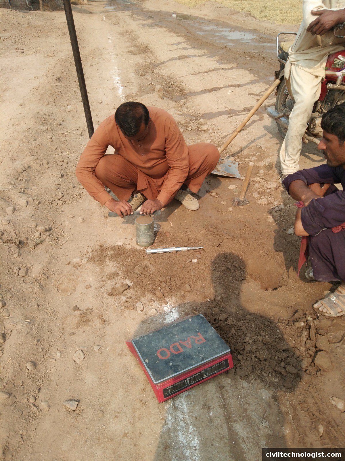
- Trim flush. Cut away the excess soil at both ends with a knife and finish flush with the straightedge, as shown in the site photo above. Both faces must be flat and level with the cutter rim.
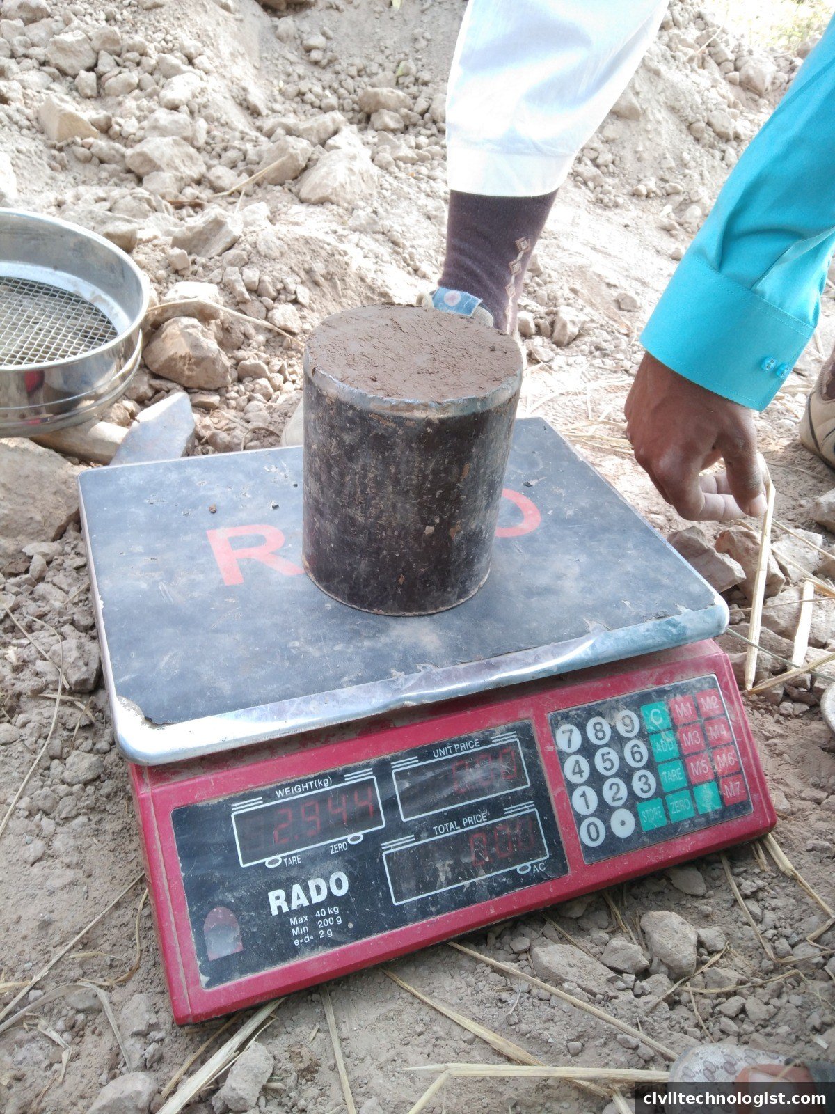
- Weigh immediately. Clean the outside of the cutter and weigh cutter + soil at once (in the site photo below, the balance reads 2.960 kg). Weighing promptly avoids moisture loss.
- Determine moisture content. Take a representative portion of the soil from the cutter and find its water content w (oven-dry or speedy tester).
- Calculate bulk density, dry density, and percentage compaction as shown below.
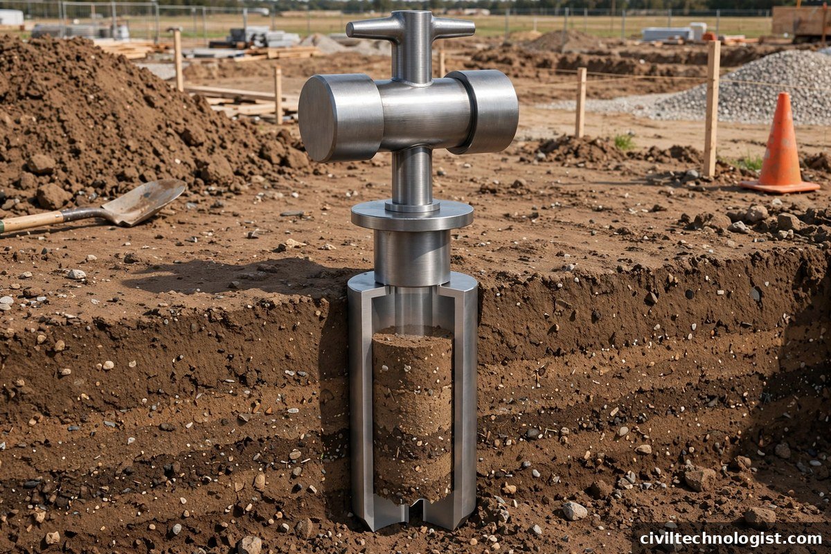

Precautions (As Per Standard Practice)
- Use this method on fine-grained soils free from aggregations, within the standard’s limit — soil 90% of which passes the 4.75 mm sieve. Coarse gravel and boulders tear the sample and damage the cutting edge.
- Keep the inside of the cutter lightly greased — a dry cutter binds the soil and disturbs the core while driving.
- Drive the cutter vertically and evenly. Tilting densifies one side of the sample and the result no longer represents the layer.
- Stop ramming when the dolly reaches the ground surface. Driving the dolly deeper compacts the soil inside the cutter and gives a falsely high density.
- Excavate the soil around the cutter before lifting — never pull or jerk the cutter out of the ground.
- Lift the cutter without tilting and keep it upright until trimming is finished.
- Trim both ends perfectly flush with the straightedge. Any bulge or hollow changes the volume the calculation assumes.
- Clean the outside of the cutter before weighing — stuck-on soil adds false mass.
- Weigh immediately after trimming. Even short delays let moisture escape and shift both readings.
- Take the moisture-content sample from the middle of the extracted core, where it best represents the layer.
- Re-calibrate the cutter volume periodically. Repeated driving wears the cutting edge and slowly changes the internal volume.
Step-by-Step Procedure — USA (ASTM D2937 Drive-Cylinder Method)
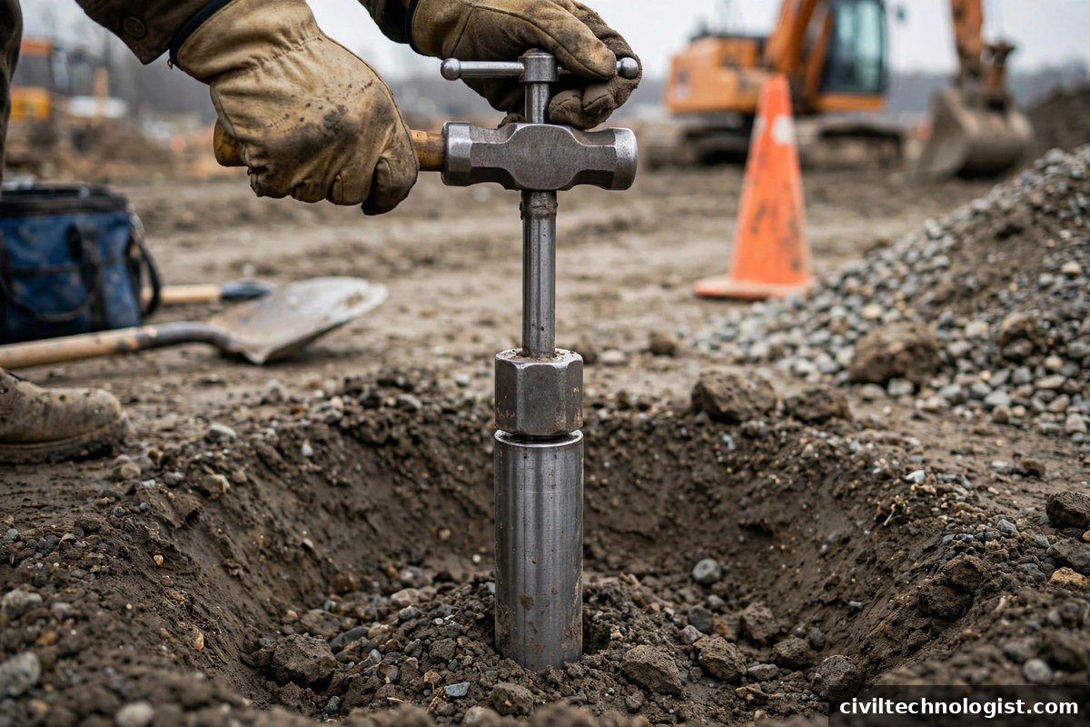
American type — the drive-cylinder method. Instead of the short wide cutter, slimmer thin-wall drive cylinders (commonly 3-inch diameter) are driven into the soil with a drive head and hammer, then trimmed and weighed the same way (illustrative image).
- Calibrate the cylinder. Measure the inside diameter and height to 0.25 mm, compute the internal volume, and weigh the empty cylinder. For acceptance testing the cylinder volume must be at least 850 cm³.
- Prepare the test level. For surface tests, level the ground. For tests below the surface, excavate down to the test elevation and level a bench.
- Drive the cylinder. Set the thin-wall cylinder on the prepared surface, fit the drive head, and drive it vertically with the sliding weight until it is fully embedded.
- Excavate and lift. Dig the soil away from around the cylinder, undercut beneath it, and lift it out without tilting or jarring.
- Trim. Cut away excess soil from the sides, then trim both ends flush and plane with the cylinder ends using the straightedge.
- Accept or reject the sample. It must be relatively undisturbed and representative, with no rocks, roots or foreign material. If the cylinder is not full, the soil is disturbed, or the cylinder was deformed during driving — discard it and take a fresh sample.
- Weigh immediately and determine the water content per ASTM D2216 (oven-dry), D4643, D4944 or D4959.
- Calculate wet density and dry density; where required, express the result as a percentage of the laboratory maximum density (ASTM D698).
Step-by-Step Procedure — UK (BS 1377-9 Core Cutter Method)
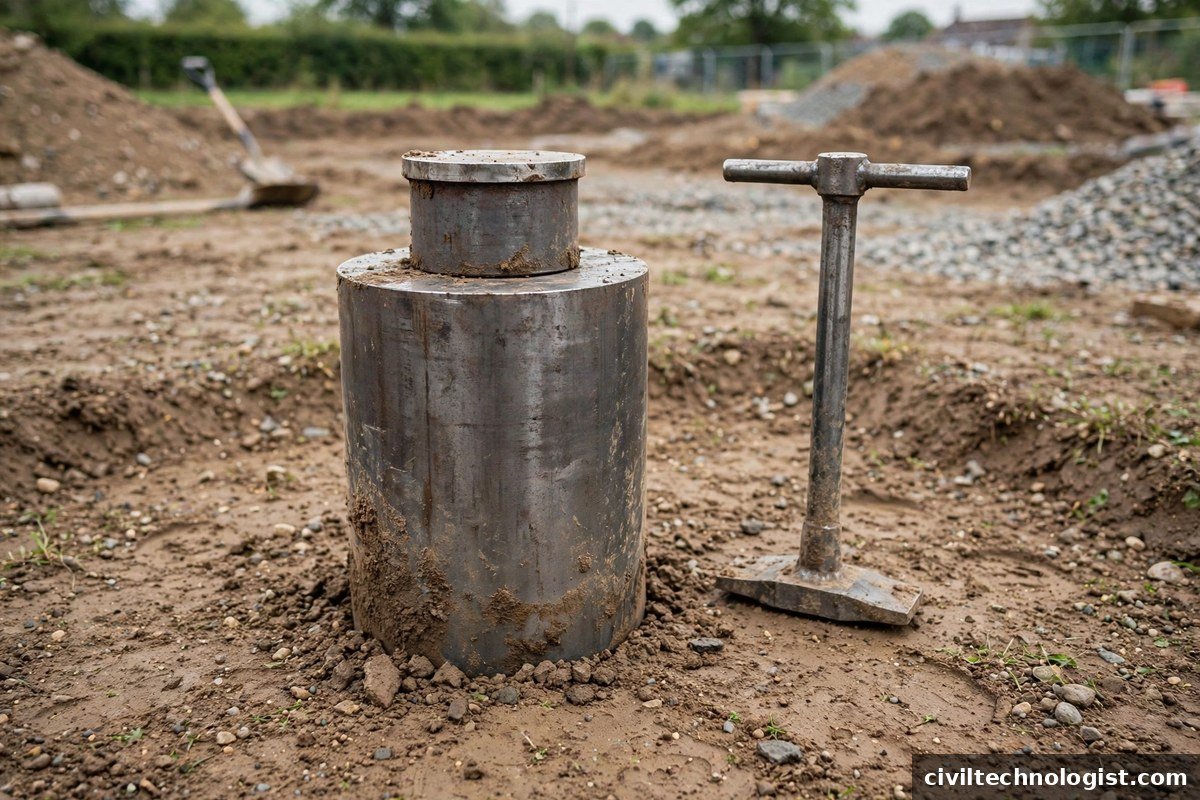
British type — the cylindrical steel core cutter with a dolly, the same 100 mm family of cutter used under IS 2720 (Part 29). The cutter is seated on levelled ground and driven in with the rammer, then excavated, trimmed flush, and weighed (illustrative image).
- Check the apparatus. Cutter 100 mm internal diameter × 130 mm long with a 3 mm bevelled cutting edge, kept lightly greased; steel dolly 25 mm high with a locating lip; steel rammer; balance reading to 1 g; 300 mm straightedge with a bevelled edge.
- Weigh the empty cutter and find its internal volume from measured dimensions.
- Level the test spot on the compacted layer.
- Jack or hammer the cutter in evenly and vertically until fully embedded, the dolly protecting the rim.
- Excavate around the cutter and lift it out carefully without disturbing the soil inside.
- Trim both ends flush with the straightedge and clean the outside of the cutter.
- Weigh immediately, then determine the moisture content by oven drying.
- Calculate bulk density, dry density and degree of compaction exactly as in the worked example above.
Core Cutter in Australia
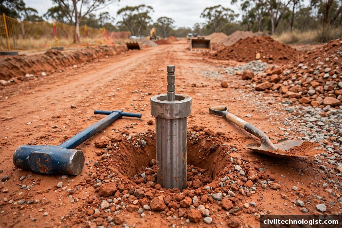
Australian type — the same cylindrical cutter-with-dolly family as the UK and IS types, shown here on a typical Australian road project with its red soil (illustrative image). Note: Australia’s own dedicated method, AS 1289.E3.3 (core cutter method for fine-grained soils, 1977), has been withdrawn — the apparatus shown belongs to the same BS/IS cylindrical family described above.
Core Cutter Around the World — More Countries
Not every country uses the core cutter as its reference method. The honest picture, checked against each country’s published standards, is below. The illustrations are generic apparatus images, not documentary evidence of national practice:
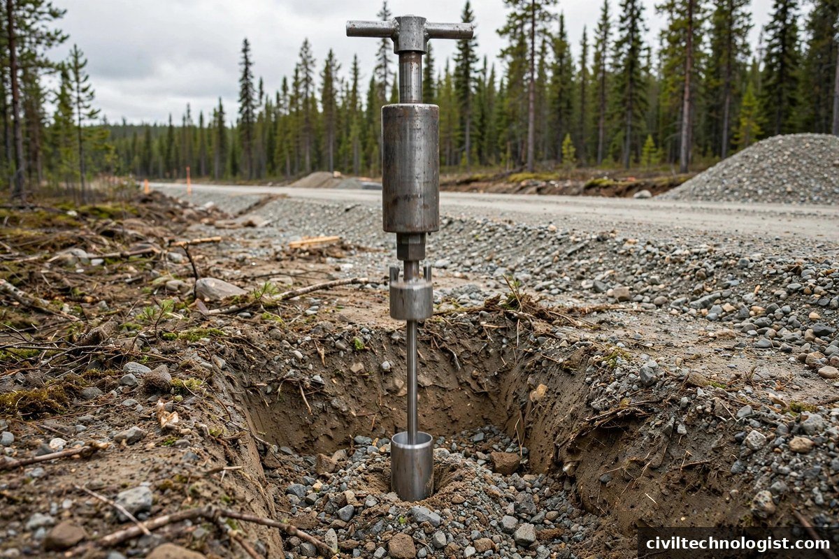
Canada — no national core-cutter standard exists; provincial highway agencies specify field density by the sand cone, rubber balloon or nuclear gauge (e.g. Alberta’s ATT-9, ATT-8 and ATT-11 test methods) (illustrative image).
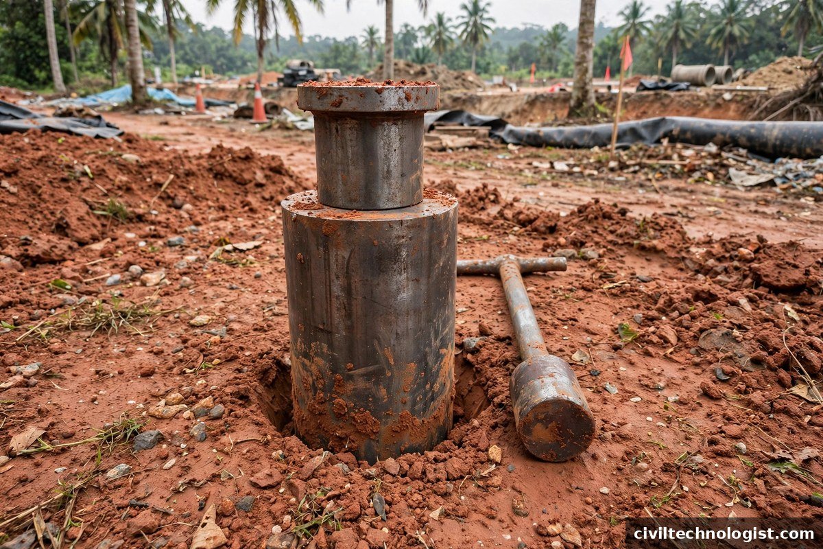
Malaysia — the JKR Standard Specification for Road Works (JKR/SPJ/1988, revised 2013) requires field density by the sand replacement method to BS 1377 / MS 1056, not by core cutter (illustrative image).
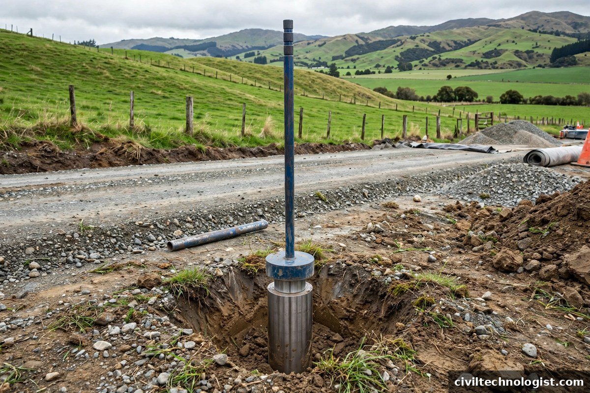
New Zealand — the direct local equivalent is the sampling-tube method for in-situ density in NZS 4402.5.1.3:1986, for fine cohesive soils into which a tube can be driven easily (illustrative image).
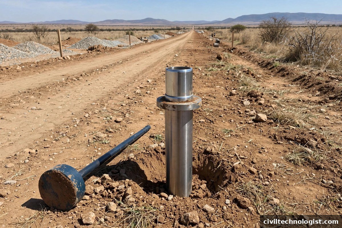
South Africa — no core-cutter method exists in the national road-testing suite; in-place dry density is measured by the sand replacement method, TMH1 Method A10(a) (illustrative image).
Procedure Comparison by Country / Standard
The test is one article worldwide because the method is nearly identical — the differences are in apparatus size and a few procedural details:
| Pakistan / India (IS 2720 Part 29) |
UK (BS 1377-9) |
USA (ASTM D2937) |
Australia (AS 1289.E3.3 — withdrawn) |
|
|---|---|---|---|---|
| Apparatus | Cutter 100 mm ID × 130 mm long; dolly 25 mm high; ~9 kg rammer | Cutter 100 mm ID × 130 mm long, 3 mm wall bevelled; dolly 25 mm high with locating lip | Thin-wall drive cylinder (≥850 cm³ for acceptance); drive head with sliding weight | Cylindrical cutter family (own method withdrawn) |
| Before driving | Lightly grease inside of cutter; weigh empty cutter | Keep cutter lightly greased; weigh empty cutter | Calibrate cylinder volume; weigh empty cylinder | BS-family practice |
| Driving | Ram until dolly is just at the ground surface — no deeper | Jack or hammer the cylinder in evenly | Drive with the sliding-weight drive head, vertically | BS-family practice |
| After extraction | Trim both ends flush with straightedge; clean outside; weigh at once | Trim flush; weigh at once | Trim ends flush with straightedge; discard sample if cylinder not full or deformed | BS-family practice |
| Moisture content | Oven-dry or speedy tester | Oven-dry | ASTM D2216 (oven), D4643, D4944 or D4959 | Oven-dry |
| Soil suitability | Fine-grained soils free from aggregations; 90% passing 4.75 mm sieve | Fine-grained cohesive soils without stones | No appreciable gravel coarser than 4.75 mm; not for organic, very hard, or low-plasticity soils | BS-family practice |
Calculation and Worked Example
Data: the 2.960 kg is the actual balance reading in the site photo above. The empty-cutter mass, moisture content and MDD below are typical assumed values for illustration — use your own measured values on site:
- Mass of cutter + soil = 2.960 kg (from the photo)
- Mass of empty cutter = 0.950 kg (assumed — weigh your own cutter)
- Mass of soil = 2.960 − 0.950 = 2.010 kg = 2010 g
- Internal volume of cutter = 1021 cm³
- Moisture content w = 12% (0.12) (assumed — measure on site)
- Laboratory MDD (from the Proctor compaction test) = 1.85 g/cm³ (assumed — from your lab report)
Step 1 — Bulk density:
ρ = 2010 / 1021 = 1.969 g/cm³
Step 2 — Dry density:
ρd = ρ / (1 + w) = 1.969 / 1.12 = 1.758 g/cm³
Step 3 — Percentage compaction:
(1.758 / 1.85) × 100 = 95.0%
Result: the layer achieves 95.0% compaction. Against a typical subgrade requirement of 95% (confirm the project specification — base courses usually demand 98–100%), this test passes.
Field note: the actual site test shown in the photos above achieved over 95% compaction — a passing result, exactly the kind of field verification this test is done for.
How Many Tests, and Where — Practical Site Guidance
- Test frequency comes from the project specification (e.g. one test per defined area of compacted layer) — never rely on a single test for a whole stretch.
- Pick representative spots: the middle of the compacted width, not the loose edges or joints where density is always lower.
- If the cutter hits a stone while driving, stop — do not force it. Move to a nearby spot and start again; a forced cutter gives a false high reading.
- If a test fails (below the required %), the layer is re-rolled/re-compacted and retested — the failed spot is not averaged away.
- Record every test properly: location, layer, date, masses, moisture, dry density and % compaction. Use a proper field density test report format so the consultant can verify each result.
Acceptance Criteria (Typical)
Always test the specification value, not this table — the contract document governs.
Core Cutter vs Sand Cone — Which to Use?
Practical note: on road projects in Pakistan, the core cutter is the daily workhorse for subgrade and earthen embankment checks, while the sand cone handles granular layers. Both feed the same acceptance calculation — field dry density against MDD. See the base course construction guide for how these layers fit together.
Common Errors on Site
- Driving the cutter tilted — densifies one side; the sample no longer represents the layer.
- Poor trimming — a bulging or hollow end changes the volume the calculation assumes.
- Delayed weighing — moisture evaporates and both density and moisture readings drift.
- Stones in the sample — a single large aggregate particle makes the density read artificially high. Reject and retest.
- Forcing the cutter through a stone — if driving gets suddenly hard, stop and relocate. Forcing compacts the soil inside and the reading is meaningless.
- Wrong method for the soil — using the cutter in gravelly material is the most common misuse; switch to sand cone.
Applicable Standards (International References)
- IS 2720 (Part 29): 1975 — Determination of Dry Density of Soils, In-Place, by the Core-Cutter Method (India; widely followed in Pakistan).
- ASTM D2937 / D2937M — Standard Test Method for Density of Soil in Place by the Drive-Cylinder Method (USA — the direct international equivalent of the core cutter test).
- BS 1377-9:1990 — Methods of test for soils for civil engineering purposes, Part 9: In-situ tests — includes the core cutter method (UK).
- AASHTO — covers in-place density by the sand cone (T 191) and nuclear methods (T 238/T 310); the core cutter/drive-cylinder approach is standardized under ASTM D2937 in US practice.
- ACI — publishes no soil field-density standard; ACI’s scope is concrete, so the core cutter test is not an ACI test.
- AS 1289.E3.3 (Australia, 1977) — historical core-cutter method for fine-grained cohesive soils; this standard has been withdrawn.
Frequently Asked Questions
What is the standard size of a core cutter?
Per IS 2720 (Part 29): 100 mm internal diameter × 130 mm height, giving an internal volume of about 1021 cm³. Always calibrate your own cutter — nominal and actual volumes differ slightly.
Can the core cutter test be used on granular sub-base?
No — not reliably. Loose granular material will not stay intact in the cutter. Use the sand cone (sand replacement) method for granular layers.
What percentage of compaction is required?
It depends on the layer and the specification — commonly 95% for embankment fill, 97–98% for subgrade, and 98–100% for base course. The project specification is the final authority.
Why is the cutter weighed immediately after trimming?
To prevent moisture loss. Even a few percent of evaporation changes both the bulk density and the moisture content reading, and the error goes straight into the dry density.
What if a stone is found inside the cutter sample?
Reject the test and repeat at a nearby spot. A stone makes the measured density unrepresentative of the soil layer.
Final Thoughts
The core cutter test is the fastest field check on compaction — one drive, one trim, one weighing, and you know whether the layer passes. Its only real weakness is the soil-type limitation, and knowing when to switch to the sand cone is what separates a technician who fills forms from one who controls quality. For the laboratory side of the same calculation, see our guide to maximum dry density and optimum moisture content.
Written by Mohsin Raza Adil — BSc Civil Engineering Technologist (NTC-registered), Pakistan.