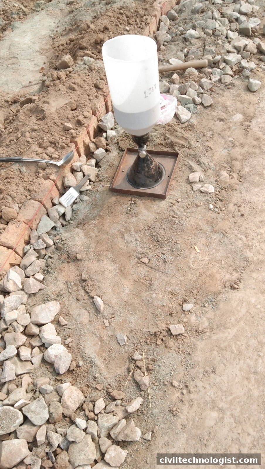
Rolling a subgrade or embankment layer means nothing until you prove the compaction is actually there. The field density test by the sand cone method is the classic field check: dig a small hole, measure its exact volume with calibrated sand, weigh the soil that came out, and compare the in-place dry density with the laboratory maximum dry density. The result — percent compaction — is what consultants accept or reject a layer on.
Governing Standards (and an Important Correction)
The correct standards for this test are:
- ASTM D1556 / D1556M — “Standard Test Method for Density and Unit Weight of Soil in Place by the Sand-Cone Method”
- AASHTO T 191 — “Density of Soil In-Place by the Sand-Cone Method”
A correction worth making openly: you may find older site documents (including the URL of this very article) referencing “ASTM D1596” for this test. ASTM D1596 has nothing to do with soil — it is the “Standard Test Method for Dynamic Shock Cushioning Characteristics of Packaging Material.” It was simply the wrong number. The soil test is D1556. You will also see “AASHO T-191” on old report formats — AASHO was renamed AASHTO in 1973, so the modern designation is AASHTO T 191.
What the Test Tells You
Field density testing answers one question: what percentage of the laboratory maximum dry density (MDD) did the roller actually achieve in the field?
Typical acceptance values (always confirm your project specifications):
| Layer | Usual minimum compaction |
|---|---|
| Embankment / subgrade | 95% of MDD |
| Sub-base / base course | 98–100% of MDD |
Percent compaction is calculated as:
% Compaction = (Field dry density ÷ Maximum dry density) × 100
The MDD and optimum moisture content (OMC) come from the laboratory Proctor test — AASHTO T 99 / T 180 or ASTM D698 / D1557 — run on the same soil.
Apparatus
- Sand cone apparatus: 1-gallon jar, detachable double cone with a valve
- Base plate with a centre hole (also used as a template for digging)
- Calibrated dry sand — clean, dry, free-flowing, of uniform grading (commonly the fraction passing a 2 mm sieve and retained on a 1 mm sieve); its bulk density must be determined in the lab
- Balance (readable to 1 g for field work)
- Moisture tins or a Speedy moisture tester for field water content
- Excavating tools: spoon, chisel, brush — plus a tray to catch every grain of excavated soil
Calibration Before Testing
Two calibrations are needed, and both are done before going to the field:
- Bulk density of the sand — fill a container of known volume with the calibrated sand (poured, not compacted, in the same way it will flow in the field), weigh it, and divide: bulk density = mass of sand ÷ volume of container.
- Cone correction — the amount of sand that fills the cone and the base-plate hole. Place the base plate on a flat surface, invert the filled apparatus over it, open the valve until flow stops, close it, and weigh the apparatus. The difference from the starting weight is the cone correction — sand that never reaches the test hole and must be subtracted every time.
Step-by-Step Procedure
- Prepare the surface. Trim a level area roughly the size of the base plate. Remove all loose, uncompacted material.
- Seat the base plate firmly so it does not rock or shift.
- Dig the hole through the plate opening, for the full depth of the compacted layer. Collect all excavated soil in the tray — nothing is left behind or brushed away.
- Weigh the excavated soil immediately (wet mass). Take a representative portion for moisture content.
- Determine moisture content — oven-dry per AASHTO T 265, or on the spot with a Speedy moisture tester (calcium carbide reacts with the soil water, and the pressure gauge reading converts to moisture percent via the supplied chart).
- Fill the hole with sand. Weigh the apparatus full of sand, invert it over the plate, open the valve, and let sand flow until it stops. Close the valve — do not tap or vibrate the apparatus — and weigh the apparatus with the remaining sand.
- Calculate: sand in hole = (sand used) − (cone correction); hole volume = sand in hole ÷ sand bulk density.
Worked Example (With Real Numbers)
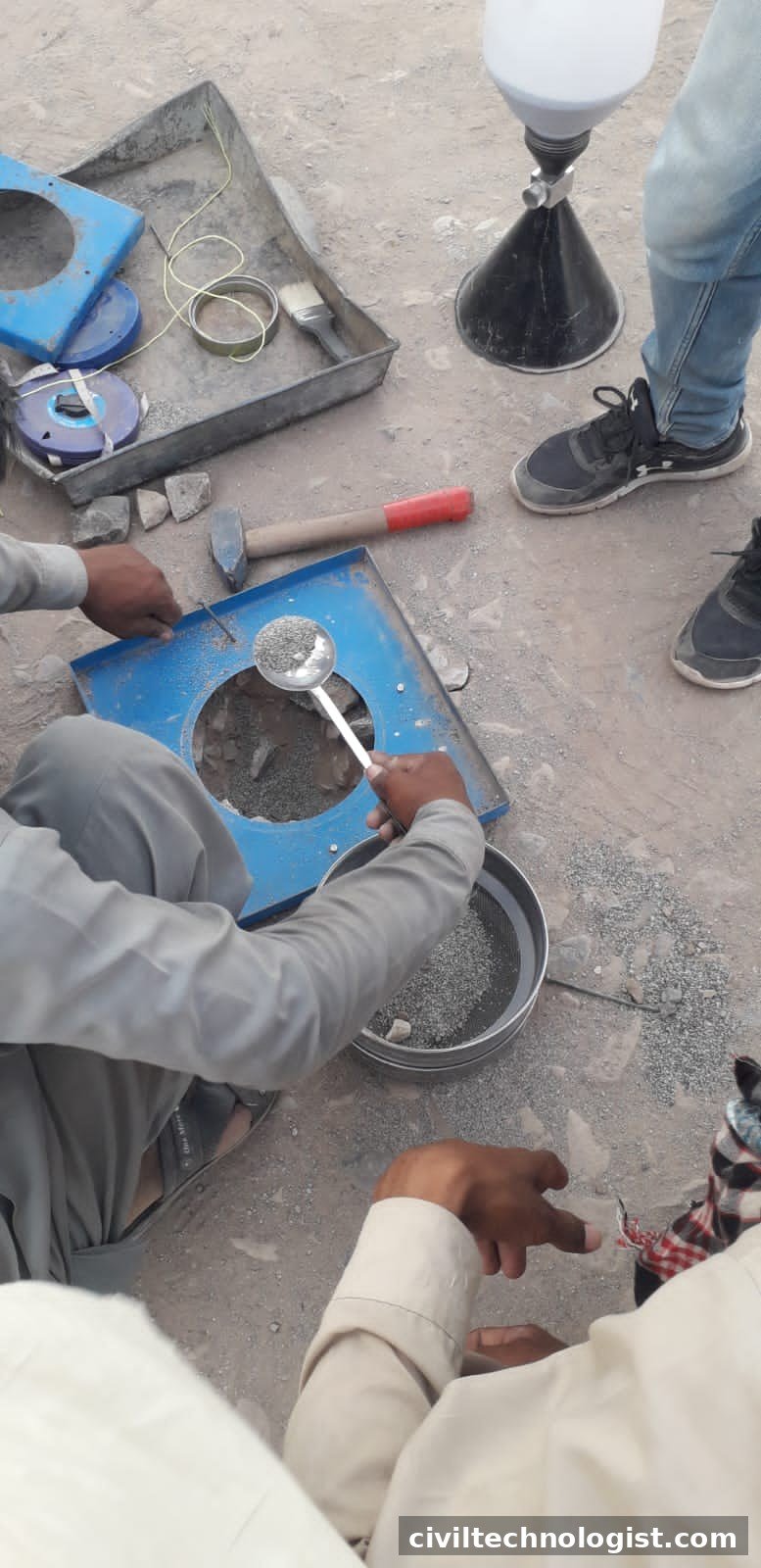
Calibrated sand flowing into the excavated test hole through the cone
A test on a compacted subgrade layer:
| Reading | Value |
|---|---|
| Mass of apparatus + sand, before | 7,200 g |
| Mass of apparatus + sand, after | 3,950 g |
| Sand used (hole + cone) | 3,250 g |
| Cone correction | 460 g |
| Sand in hole | 2,790 g |
| Bulk density of calibrated sand | 1.42 g/cm³ |
Step 1 — Hole volume
Volume = 2,790 ÷ 1.42 = 1,965 cm³
Step 2 — Wet (bulk) density
Mass of excavated wet soil = 3,850 g
Wet density = 3,850 ÷ 1,965 = 1.96 g/cm³
Step 3 — Dry density (moisture by Speedy = 9.5%)
Dry density = Wet density ÷ (1 + w) = 1.96 ÷ 1.095 = 1.79 g/cm³
Step 4 — Percent compaction
Laboratory MDD = 1.88 g/cm³ (OMC = 10.2%)
% Compaction = (1.79 ÷ 1.88) × 100 = 95.2%
Required: 95% → the layer passes. Also note the field moisture (9.5%) is close to OMC (10.2%) — soil compacted near OMC compacts most efficiently, which is exactly what the numbers show.
Field Density Test Report Format
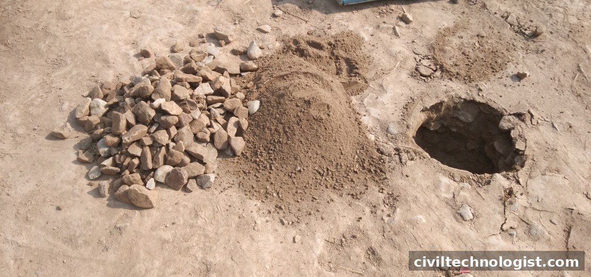
Excavated soil from the test hole, collected for weighing
Below is a practical report layout adapted from a typical Highway Department sand-cone report (AASHTO T-191). A blank, ready-to-use version of this report format can be downloaded here: Download the blank FDT report template (DOCX)
A. General
| # | Item |
|---|---|
| 1 | FDT Test No. |
| 2 | Chainage / location |
| 3 | Layer No. and depth of hole (cm) |
| 4 | Date of testing |
B. Moisture Content
| # | Item |
|---|---|
| 1 | Can No. |
| 2 | Mass of empty can (g) |
| 3 | Mass of can + wet soil (g) |
| 4 | Mass of can + dry soil (g) |
| 5 | Mass of water (g) |
| 6 | Mass of dry soil (g) |
| 7 | Water content (%) |
| 8 | Speedy moisture reading (%) |
C. Field Density
| # | Item |
|---|---|
| 1 | Mass of soil excavated from hole (g) |
| 2 | Mass of sand + apparatus, before (g) |
| 3 | Mass of sand + apparatus, after (g) |
| 4 | Mass of sand used, hole + cone (g) |
| 5 | Cone correction — sand to fill cone (g) |
| 6 | Mass of sand in hole (g) |
| 7 | Bulk density of calibration sand (g/cm³) |
| 8 | Volume of hole (cm³) |
| 9 | Wet density of soil (g/cm³) |
| 10 | Dry density of soil (g/cm³) |
| 11 | Maximum dry density, lab (g/cm³) |
| 12 | Optimum moisture content (%) |
| 13 | Compaction obtained (%) |
| 14 | Compaction required (%) |
| 15 | Result: Pass / Fail |
The report is signed by the contractor’s and consultant’s representatives, with chainage, request number, and remarks.
Common Mistakes That Ruin Results
- Using damp or mixed sand. Sand must be oven-dry and from the same calibrated batch. Damp sand bridges in the cone and under-fills the hole.
- Skipping the cone correction. The cone holds a surprising amount of sand; forgetting it inflates the hole volume and under-reports density.
- Losing excavated soil. Every grain that falls outside the tray is density you “lose” — the soil mass must be complete.
- Rocking base plate or a ragged hole. An unstable plate lets sand leak under it; an over-dug, bell-shaped hole is fine (sand measures whatever shape), but undercutting the plate is not.
- Vibrating the apparatus while sand flows — it densifies the sand in the hole and shrinks the measured volume.
- Wrong moisture value. A Speedy reading is fast but less precise than oven drying; know which one your specification accepts.
Field Density Calculator (Sand Cone)
Calculate field density & compaction from sand-cone readings
Frequently Asked Questions
How many field density tests are needed per layer?
Follow the project specification. A common field rule is one test per 500–1000 m² of compacted layer, with at least one test per day’s work — but the specification governs, not the rule of thumb.
Sand cone or nuclear density gauge?
The sand cone is the reference method — cheap, simple, and accepted everywhere. Nuclear gauges are faster but need licensing, safety handling, and regular calibration against sand-cone results.
Can the sand cone be used on base course with large stone?
ASTM D1556 suits soils with particles up to about 38 mm (1½ in.). For coarser base material, use the large-hole method (ASTM D4914) or the rubber-balloon method (ASTM D2167).
What if the field moisture is much higher than OMC?
Stop and dry the layer back (aeration, re-mixing) before rolling. Compacting wet-of-optimum soil wastes roller passes and can pump fines to the surface.
Final Thoughts
The sand cone test is nearly a century old and still the backbone of earthwork quality control, because it is direct: it measures the actual soil in the actual layer. Calibrate the sand honestly, dig the hole carefully, and the arithmetic in the worked example above is all that stands between you and a defensible pass/fail decision.
Written by Mohsin Raza Adil — BSc Civil Engineering Technologist (NTC-registered), Pakistan.

Mohsin Raza Adil
BSc Civil Engineering Technologist (NTC-registered), Pakistan. I write practical, field-tested guides on construction materials, soil testing and site engineering — the way it is actually done on site.

7 thoughts on “Field Density Test (Sand Cone Method): Procedure, Calculation & Report Format”