If you have ever read a soil investigation report, you have met the SPT N-value. It is the single most quoted number in geotechnical reports across Pakistan and around the world — a simple count of hammer blows that, when corrected and interpreted properly, tells you how dense or stiff the ground is, what bearing pressure you can use, and whether you need piles or a raft.
The Standard Penetration Test (SPT) is the most widely used in-situ soil test in the world. It is cheap, it needs no special laboratory equipment on site, and — unlike most field tests — it hands you an actual soil sample along with the number. But the raw blow count is only half the story. The N-value must be corrected for overburden pressure and, in some soils, for dilatancy before it goes anywhere near a design chart. This guide covers the apparatus, the step-by-step procedure under both ASTM D1586 and BS EN ISO 22476-3, the corrections with a worked example, and how to interpret the results.
What Is the Standard Penetration Test?
The SPT measures the penetration resistance of soil in a borehole. A standard split-barrel sampler (often called a split-spoon sampler) is driven into the ground at the bottom of the borehole by repeated blows of a standard hammer. The number of blows needed to drive the sampler a set distance is the N-value (blows per 300 mm of penetration).
The test is used to:
- Estimate the relative density of sands and gravels
- Judge the consistency of clays and silts
- Estimate bearing capacity and settlement of shallow foundations
- Assess liquefaction potential of saturated sands in seismic design
- Obtain disturbed soil samples for classification, moisture content, and gradation testing
It was developed in North America in the 1920s–30s, adopted into Terzaghi and Peck’s Soil Mechanics in Engineering Practice (1948), and has been standardised ever since as ASTM D1586 (with AASHTO T206 as the equivalent highway-agency version). In the UK and Europe the test is covered by BS EN ISO 22476-3 (Geotechnical investigation and testing — Field testing — Part 3: Standard penetration test), which replaced the older BS 1377 Part 9.
Practical note: The SPT is an index test, not a precision instrument. Two drill crews on the same site can report noticeably different N-values for the same layer, mainly because of differences in hammer energy. Treat every N-value as an approximation with judgment applied — never as an exact soil property.
SPT Apparatus
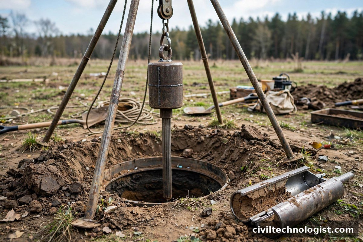
The standard equipment consists of:
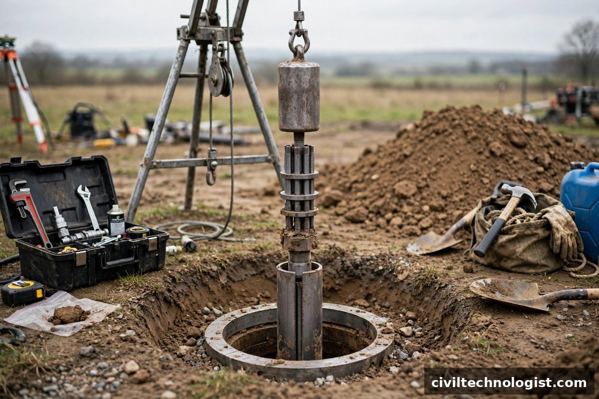
- Split-barrel (split-spoon) sampler — a thick-walled steel tube, 51 mm (2 in) outside diameter and about 650 mm long, split lengthwise into two halves so the sample can be opened up and examined. It has a hardened cutting shoe at the bottom and a head with a ball check valve (which helps retain loose sand when the sampler is pulled out).
- Drive hammer — 63.5 kg (140 lb) mass, dropped from a height of 760 mm (30 in). Safety hammers and automatic trip hammers are the common types; automatic hammers deliver more consistent energy.
- Drill rods — connect the hammer/anvil to the sampler.
- Borehole equipment — tripod or drilling rig, casing or drilling fluid to keep the hole open, and tools to clean the bottom of the hole before testing.
The 63.5 kg hammer falling 760 mm is the heart of the test — every correlation ever published for SPT assumes this energy input. If a non-standard hammer is used, the results are not directly comparable.
SPT Procedure (Step by Step)
The procedure below follows ASTM D1586; BS EN ISO 22476-3 follows the same essentials (63.5 kg hammer, 760 mm drop, 300 mm test drive after a seating drive).
- Advance the borehole to the test depth and clean the bottom of the hole carefully. Loose, disturbed soil left at the bottom will give a falsely low N-value — this is one of the most common sources of bad data.
- Lower the split-barrel sampler on the drill rods to the bottom of the hole. Make sure the sampler sits on undisturbed soil.
- Seating drive: drive the sampler the first 150 mm (6 in) and record the blows. This seating drive is not included in the N-value — it simply beds the sampler into any minor disturbance at the hole bottom.
- Test drive: drive the sampler a further 300 mm (12 in) in two 150 mm increments, recording the blows for each increment separately.
- The N-value is the sum of the blows for the second and third 150 mm increments — i.e. blows per 300 mm of penetration after seating.
- Withdraw the sampler, open the split barrel, and log the sample: soil description, borehole number, depth, N-value, date. Preserve it in a sealed bag or jar for the lab.
- Repeat at the next test depth — typically every 1.0–1.5 m, or at every change of soil stratum.
Refusal: If 50 blows fail to advance the sampler through a 150 mm increment, stop driving. Record it as refusal (e.g. “50/75 mm” — 50 blows for 75 mm penetration). Continuing to hammer a refused sampler damages the equipment and tells you nothing new.
Practical note: On site, watch the driller, not just the numbers. A blow count written down without checking that the hole bottom was clean, the hammer drop was a true 760 mm, and the rods were vertical is a number you cannot trust. Good practice is for the supervising engineer or technologist to be present for at least the first few tests of a new borehole.
Split-Barrel Sampling — Why the Sample Matters
One reason the SPT has survived for a century is that every test produces a physical soil sample. These are disturbed samples (the thick-walled sampler remoulds the soil as it drives in), but they are perfectly adequate for:
- Visual soil classification and logging of strata changes
- Moisture content determination
- Grain-size analysis (sieve/hydrometer)
- Atterberg limits on the fine fraction
The sample should be labelled immediately — borehole number, depth, N-value, date — because an unlabelled bag of soil in the site store is worthless by the next morning. If the sample is loose saturated sand that tends to fall out, the sampler’s check valve and a sample catcher retain it.
N-Value Corrections
The raw field N-value is never used directly in design correlations. Two corrections are applied in sequence, and a third (energy) correction is standard in modern practice.
1. Overburden Pressure Correction
The same sand gives a low N-value near the surface and a high N-value at depth, simply because confining pressure increases with depth. To compare N-values from different depths, they are normalised to a standard effective overburden stress.
The widely used Gibbs and Holtz (1957) correction:
N₁ = N × 350 / (σ’ + 70)
where N is the observed N-value and σ’ is the effective overburden stress at the test depth in kPa. This correction applies when σ’ is less than about 280 kPa. (Some guidance caps the ratio N₁/N between 0.45 and 2.0 — if the computed ratio exceeds 2, halve the corrected value for design.)
2. Dilatancy (Water Table) Correction
In fine saturated sands and silts below the water table, the rapid hammer blows generate negative pore-water pressure (the soil tries to dilate but water cannot flow in fast enough), which temporarily stiffens the soil and inflates the blow count. Terzaghi and Peck’s correction:
Nc = 15 + (N₁ − 15) / 2
This applies only when N₁ exceeds 15, and only for fine saturated sand/silt below the water table. If N₁ ≤ 15, no correction is needed: Nc = N₁.
3. Energy Correction (N₆₀)
Different hammer systems deliver different energy — a rope-and-cathead rig may deliver 30–60% of the theoretical energy while an automatic trip hammer delivers 80–90%. Modern correlations are normalised to 60% energy:
N₆₀ = N × (ER / 60)
where ER is the measured (or estimated) energy ratio in percent. ASTM D6066 covers energy measurement of SPT hammers. If you don’t know the hammer efficiency, say so in the report rather than guessing.
Correction Summary Table
| Correction | When applied | Formula |
|---|---|---|
| Overburden (N₁) | All granular soils; σ’ < ~280 kPa | N₁ = N × 350 / (σ’ + 70) |
| Dilatancy (Nc) | Fine saturated sand/silt below water table, N₁ > 15 | Nc = 15 + (N₁ − 15) / 2 |
| Energy (N₆₀) | Always, when hammer efficiency is known | N₆₀ = N × ER / 60 |
Worked Example — From Field Blows to Design N-Value
Field data: At 11 m depth in a borehole, the sampler recorded 8 blows for the seating drive, then 11 and 13 blows for the two test increments. The water table is at 5 m. The soil is fine saturated sand. Unit weight above the water table is 18 kN/m³; saturated unit weight below is 20 kN/m³.
Step 1 — Observed N-value:
N = 11 + 13 = 24 (the 8 seating blows are discarded).
Step 2 — Effective overburden stress at 11 m:
σ = (5 × 18) + (6 × 20) = 90 + 120 = 210 kPa
u = 6 × 9.81 = 58.9 kPa
σ’ = 210 − 58.9 = 151 kPa
Step 3 — Overburden correction:
N₁ = 24 × 350 / (151 + 70) = 24 × 350 / 221 = 24 × 1.584 = 38
Step 4 — Dilatancy correction (fine saturated sand below water table, N₁ = 38 > 15):
Nc = 15 + (38 − 15) / 2 = 15 + 11.5 = 26.5 → 27
Result: The corrected N-value for design is 27 — noticeably different from the field count of 24. From the interpretation table below, N = 27 indicates medium-dense sand.
Interpreting the N-Value
Cohesionless Soils — Relative Density
| N-value | Relative density |
|---|---|
| 0–4 | Very loose |
| 4–10 | Loose |
| 10–30 | Medium dense |
| 30–50 | Dense |
| > 50 | Very dense |
Cohesive Soils — Consistency
| N-value | Consistency |
|---|---|
| 0–2 | Very soft |
| 2–4 | Soft |
| 4–8 | Medium (firm) |
| 8–15 | Stiff |
| 15–30 | Very stiff |
| > 30 | Hard |
These are empirical guides, not exact boundaries. For cohesive soils the SPT is a rough indicator — an unconfined compression or vane shear test gives a far better measure of undrained shear strength. Commonly used approximate correlations include undrained shear strength cu ≈ 6–7 × N (kPa) for clays, and the friction angle of sands increasing from about 28° at N = 4 to over 40° at N > 50 — always check which correlation your design code endorses before using one.
Limitations of the SPT
- Operator and equipment dependent — hammer type, drop height control, rod length, and borehole condition all shift the result. Energy correction helps but is rarely measured on small projects.
- Poor in gravels and cobbles — large particles jam the sampler and cause premature refusal that has nothing to do with soil density.
- Disturbed samples only — you cannot get strength or compressibility parameters directly from the SPT sample.
- Crude in very soft clays — the sampler may sink under its own weight (N = 0), which tells you the soil is very soft but nothing more.
- Corrections are empirical — the overburden and dilatancy formulas are based on limited test data; applying them mechanically without judgment is a classic junior-engineer mistake.
- Not a substitute for laboratory testing where settlement or stability calculations need real compressibility and shear strength data.
Frequently Asked Questions
What is the SPT N-value?
The number of hammer blows required to drive the split-barrel sampler 300 mm into the soil, after an initial 150 mm seating drive. The standard hammer is 63.5 kg dropped from 760 mm.
Why is the first 150 mm of driving not counted?
The seating drive beds the sampler through any loose or disturbed soil at the bottom of the borehole. Counting it would mix disturbed-zone resistance into the measurement.
Which is correct — ASTM D1586 or BS EN ISO 22476-3?
Both describe essentially the same test: 63.5 kg hammer, 760 mm drop, 150 mm seating drive plus 300 mm test drive. ASTM D1586 (with AASHTO T206) is the American standard; BS EN ISO 22476-3 is the European/UK standard. Use whichever your project specification calls for.
When is the dilatancy correction applied?
Only for fine sands and silts below the water table, and only when the overburden-corrected N₁ exceeds 15. In coarse sands above the water table, it is never applied.
What does SPT refusal mean?
Refusal — typically 50 blows for less than 150 mm of penetration — means the sampler cannot be driven further with the standard energy. It indicates very dense soil, gravel, cobbles, or rock, and the test is stopped at that depth.
Can the SPT be used in clay?
Yes, as a rough indicator of consistency (see the table above), but it is a poor tool for measuring clay strength. Prefer unconfined compression, triaxial, or vane shear tests for design values in cohesive soils.
Final Thoughts
The SPT earns its place on every site investigation because it is fast, cheap, and gives you both a number and a sample. Its weakness is that the number is raw — hammer energy, overburden stress, and pore-water effects all distort it. The engineer who corrects the N-value properly and reads it with judgment gets reliable foundation decisions out of it; the one who copies the field blow count straight into a bearing-capacity formula is designing on sand, in the worst sense.
Written by Mohsin Raza Adil — BSc Civil Engineering Technologist (NTC-registered), Pakistan.

Mohsin Raza Adil
BSc Civil Engineering Technologist (NTC-registered), Pakistan. I write practical, field-tested guides on construction materials, soil testing and site engineering — the way it is actually done on site.

2 thoughts on “Standard Penetration Test (SPT): Complete Guide — Procedure, N-Value Correction & Interpretation”