Most houses in Pakistan stand on walls, not on framed columns. In a load-bearing building, the walls do two jobs at once: they divide the space and they carry every load above them — roof, floors, parapets — down to the foundation. When these walls are designed properly, the building is safe and economical; when they are not, the first signs of trouble (cracking at corners, bowing walls) can take years to appear, which is exactly why a careful calculation matters.
This article walks you through the design principles, the types and properties of masonry used for load-bearing walls, and a complete worked example you can follow number by number.
What Is a Load-Bearing Wall?
A load-bearing wall is a structural wall that supports the weight of floors and roofs above it and transfers those loads vertically to the foundation. Unlike partition walls (which only support their own weight), removing or weakening a load-bearing wall changes the building’s structure — which is why old-house owners are told never to demolish a wall without an engineer checking it first.
In residential buildings of one to three storeys, load-bearing masonry remains the most common structural system in Pakistan because it is economical, fire-resistant, and easy to build with locally available bricks and mortar.
Types of Walls Used as Load-Bearing Walls
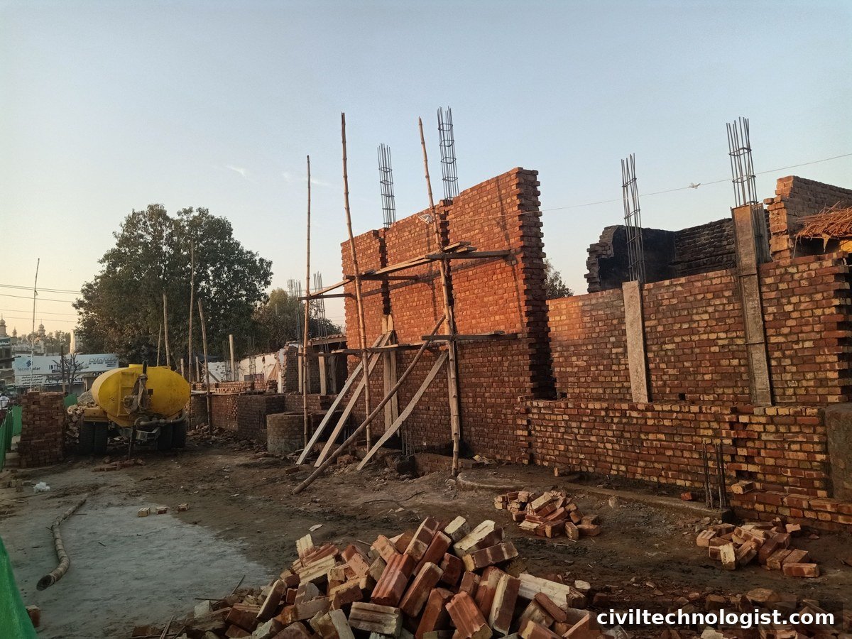
The load-bearing capacity of a wall depends on what it is made of. The main options are:
| Wall type | Typical thickness | Where it is used |
|---|---|---|
| Solid clay brick wall | 230 mm (9 in) | Standard external and internal load-bearing walls in houses |
| Solid concrete block wall | 150–200 mm | Modern construction, industrial buildings |
| Stone masonry wall | 450–600 mm | Boundary walls, old buildings, hilly areas |
| Hollow block wall | 200 mm | Usually partitions or infill; load-bearing only with design |
Materials and properties
- Clay bricks: Good compressive strength when well burnt; standard first-class bricks in Pakistan crush at roughly 7–14 N/mm². Water absorption should not exceed 20% for first-class bricks, or the mortar bond and durability suffer.
- Concrete blocks: More uniform than clay bricks and faster to lay, but heavier per unit and more expensive where burnt bricks are cheap and plentiful.
- Mortar: The mortar type (cement:sand) directly controls the masonry strength. Common site mixes are 1:4 and 1:6. Richer mortar (1:3–1:4) is used for load-bearing work; leaner mixes are only for non-structural walls.
Practical note: On site, mortar quality is judged the quick way first: a handful of mixed mortar should hold together when squeezed and not crumble — and bricks should always be soaked in water before laying in hot weather, because dry bricks suck the water out of the mortar and weaken the bond.
Design Principles of Load-Bearing Walls
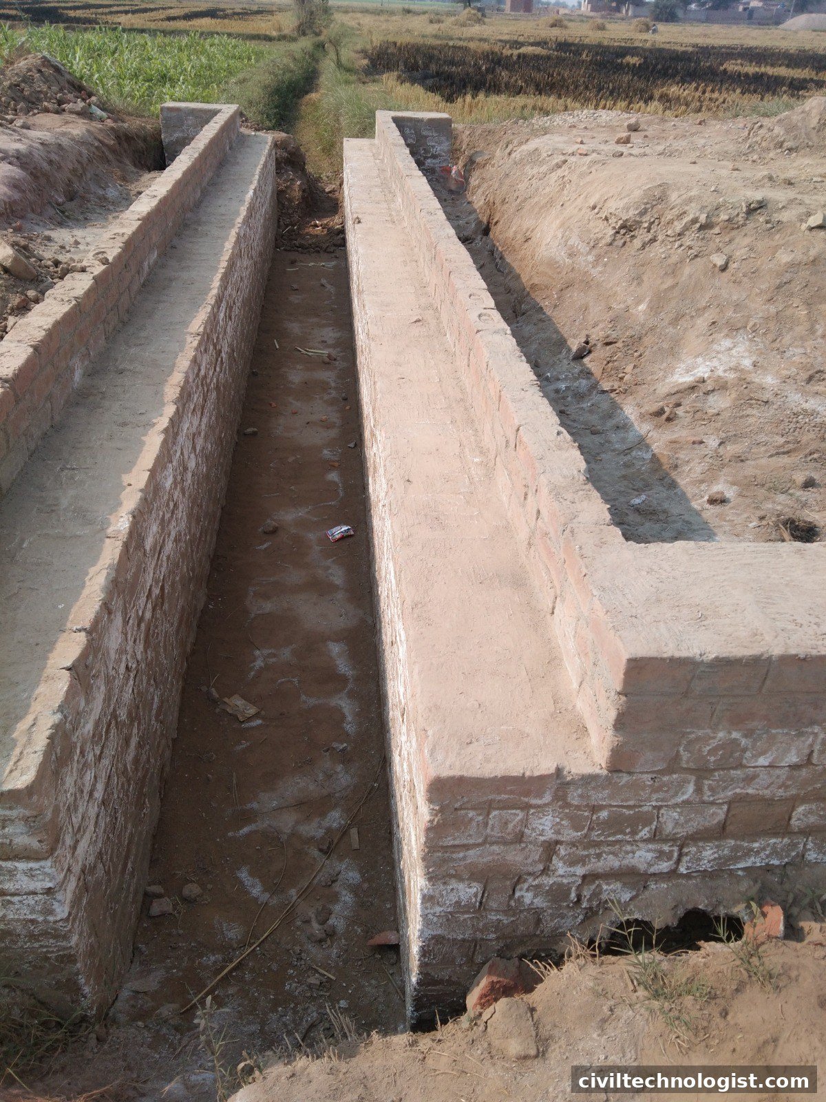
1. Load path — keep it vertical and continuous
Every load must have an uninterrupted path from roof to foundation. Walls should sit directly above walls below (or above beams designed for them). A wall floating over a doorway or window without a proper lintel breaks the load path.
2. Concentric loading — keep loads in the middle of the wall
Masonry is strong in compression but very weak in tension. Loads should act at or near the centre of the wall thickness. When a slab bears on the inner edge of a wall, it pushes eccentrically and puts one face of the wall in tension. Codes therefore require a minimum eccentricity to be assumed in design — ACI 530 (TMS 402) assumes a minimum eccentricity of 0.1t (one-tenth of the wall thickness), and BS 5628-1 treats any eccentricity up to t/6 as within the “middle third” of the wall.
3. Slenderness — a wall can buckle
A tall thin wall can fail by buckling long before the brick itself crushes. The slenderness ratio (effective height ÷ effective thickness) must stay within code limits:
λ = h_eff / t_eff ≤ 27 (BS 5628-1)
For a wall with simple (pinned) supports at floor and roof, the effective height is approximately the clear storey height. Keeping λ low is why external walls are typically 230 mm thick even when a strength check alone would allow less.
4. Minimum bearing and proper supports
Roof slabs and beams need adequate bearing length on the wall (at least half the wall thickness is a common rule), and the wall itself must be laterally supported at each floor level.
5. Openings need lintels
Every door and window opening interrupts the wall. RCC lintels carry the load over openings back into the wall piers beside them. An opening should never be cut into a load-bearing wall without a lintel sized for the load above it.
6. Workmanship is part of the strength
Masonry strength in the tables assumes plumb walls, full mortar joints, and proper curing. A wall built out of plumb or with dry joints loses a large part of its calculated capacity. This is the design assumption most often violated on site — and the hardest to check later.
Design Inputs
Before any calculation, collect these values:
| Input | Symbol | Typical value (Pakistan) |
|---|---|---|
| Wall clear height | h | 3.0 m (storey height) |
| Wall thickness | t | 230 mm (9 in brick) |
| Masonry unit weight | γ | ≈ 18.5 kN/m³ (brick masonry) |
| Roof slab thickness | d | 150 mm |
| Slab dead load (self-weight + finishes) | q_D | 3.6 + 1.0 = 4.6 kN/m² |
| Roof live load (accessible flat roof) | q_L | 1.9 kN/m² |
| Tributary width (half the slab span) | b | 2.0 m (for 4.0 m span) |
| Parapet height | h_p | 1.0 m |
| Masonry compressive strength (brick unit) | f_b | ≥ 10 N/mm² (first-class brick) |
Calculation Steps
Step 1 — Axial load per metre run of wall, P
P = self-weight of wall + parapet + slab dead load + live load

Wall self-weight   = t × h × γ  (kN/m)
Parapet            = t × h_p × γ (kN/m)
Slab dead load     = q_D × b (kN/m)
Live load          = q_L × b (kN/m)
Step 2 — Compressive stress in the wall
σ = P / A, where A = 1000 mm × t (cross-section per metre run)
Step 3 — Allowable compressive stress, σ_allow
From the empirical design table (TMS 402/ACI 530, Appendix A): for solid clay brick masonry with brick unit strength ≈ 10 MPa (1500 psi) and Type N mortar, the allowable compressive stress is approximately 0.97 N/mm².
Step 4 — Strength check: σ ≤ σ_allow
Step 5 — Slenderness check: λ = h_eff / t_eff ≤ 27
Worked Example
Given: Ground-floor external wall of a single-storey house. 230 mm solid brick wall, 3.0 m clear height, carrying a 150 mm RCC roof slab spanning 4.0 m. 1.0 m high brick parapet above the roof.
Step 1 — Loads per metre run
- Wall self-weight = 0.23 m × 3.0 m × 18.5 kN/m³ = 12.8 kN/m
- Parapet = 0.23 m × 1.0 m × 18.5 kN/m³ = 4.3 kN/m
- Slab dead load = 4.6 kN/m² × 2.0 m = 9.2 kN/m
- Live load = 1.9 kN/m² × 2.0 m = 3.8 kN/m
Total service axial load, P = 12.8 + 4.3 + 9.2 + 3.8 = 30.1 kN/m ≈ 30 kN/m
Step 2 — Stress
Cross-section per metre: A = 1000 × 230 = 230,000 mm²
σ = 30,000 N ÷ 230,000 mm² = 0.13 N/mm²
Step 3 — Allowable stress
Assuming first-class bricks (unit strength ≥ 10 N/mm²) with Type N (1:4–1:6) mortar → σ_allow ≈ 0.97 N/mm² (TMS 402/ACI 530 empirical design table).
Step 4 — Strength check
0.13 ≤ 0.97 → Adequate (utilization ≈ 13%)
Step 5 — Slenderness check
λ = 3000 mm ÷ 230 mm = 13.0 ≤ 27 → Adequate
Frequently Asked Questions
What is the minimum thickness of a load-bearing wall?
In Pakistan, external load-bearing walls are typically 230 mm (9 in). Walls of 115 mm (4.5 in) are partitions only and should not carry floors or roofs.
Can a 4-inch brick wall be load-bearing?
No. A 115 mm (4.5 in) single-brick wall is too slender to carry structural loads safely and is used only as a partition or cladding wall.
What mortar mix should be used for load-bearing walls?
A 1:4 (cement:sand) mix is standard for load-bearing brickwork in Pakistan. Leaner 1:6 mixes are acceptable only for non-load-bearing walls.
Why does slenderness matter more than strength for low walls?
Because masonry crushes at very high stress, but a tall thin wall buckles at much lower stress. For typical 3 m storey walls, the slenderness limit — not the compressive strength — usually controls the design.
Written by Mohsin Raza Adil — BSc Civil Engineering Technologist (NTC-registered), Pakistan.

Mohsin Raza Adil
BSc Civil Engineering Technologist (NTC-registered), Pakistan. I write practical, field-tested guides on construction materials, soil testing and site engineering — the way it is actually done on site.


2 thoughts on “Load-Bearing Wall Design: Principles, Steps and Worked Calculation Example”